Insights and media
New house building news and related articles.

Latest news
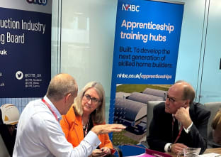
Training and qualifications
The Rt Hon Baroness Smith meets homebuilders to address construction skills shortage
Awards and events
UK’s best site managers recognised by NHBC for raising standards in house building

Company
NHBC announces the appointment of Paul Turner as new CEO
Company
NHBC welcomes Chancellor’s Spending Review announcement
Latest insights

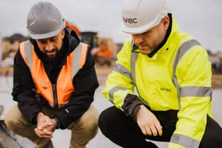
Skills gap
In conversation with Roger Morton: the skills gap
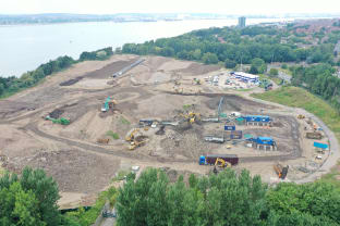
Building & design
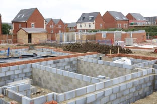
The land remediation process - understanding the pathway to warranty and insurance
Market trends
New home registrations rise in Q1 with developers encouraged by government focus on housing, reports NHBC

Building & design